Summary As semiconductor fabs scale wafer output and process complexity, the number of point-of-use abatement devices per fab bay continues to multiply. A single CVD cluster tool with three or four process chambers operating in parallel may require an equivalent number of POU scrubbers — each consuming sub-fab floor space, facility utilities, and maintenance labor hours. Consolidating multi-chamber exhaust into fewer, higher-capacity abatement units is one of the most direct levers available to reduce sub-fab equipment density without compromising destruction efficiency. The WOFLY GTHW 600, with 600 LPM gas capacity and six KF40 process gas inlets, is engineered specifically for this consolidation strategy: one unit serving up to six process chambers simultaneously, reducing POU scrubber count while maintaining gas-specific treatment performance across CVD, PECVD, and dry etch exhaust streams. This article examines the operational and economic case for multi-chamber abatement consolidation using the GTHW 600 as a reference platform, covering facility integration requirements, maintenance access design, and total cost of ownership drivers.
Part 1: The Sub-Fab Equipment Density Problem
Walk through the sub-fab level of any modern 300mm wafer fab and the visual reality is unmistakable: point-of-use abatement equipment occupies an increasing fraction of available floor space. Each process tool on the cleanroom floor above requires at least one POU scrubber in the sub-fab below. As fabs add capacity — more tools, more chambers per tool, more process steps per wafer — the sub-fab equipment count grows proportionally.
This density creates three operational problems that compound over time:
Floor space competition. Sub-fab utility routing — process cooling water, exhaust ductwork, bulk gas lines, electrical cable trays — competes with equipment footprint. When POU scrubber count reaches a critical density, maintenance access clearances shrink to the point where equipment service requires removing adjacent units — multiplying the labor hours for what should be a single-unit procedure.
Utility consumption multiplication. Each POU scrubber draws power, nitrogen, compressed dry air, and cooling water independently. Ten 60-LPM scrubbers consume approximately the same total gas capacity as one 600-LPM unit, but with ten sets of parasitic utility loads — ten control systems, ten N2 purge circuits, ten sets of valve actuation pneumatics. Consolidation eliminates redundant parasitic loads, directly reducing facility utility consumption per unit of gas treated.
Maintenance labor multiplication. Each POU scrubber requires periodic preventive maintenance — inlet inspection, sensor calibration, water circuit cleaning, heater element verification. Ten independent units mean ten sets of PM procedures, ten sets of maintenance records, and ten opportunities for a missed PM interval to trigger an unscheduled downtime event. Consolidation reduces PM touchpoints without reducing treatment capacity.
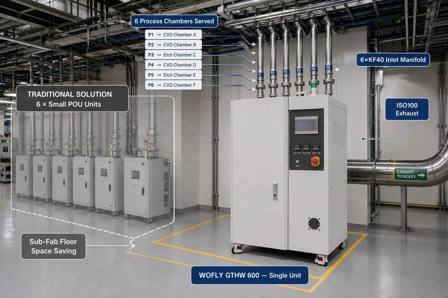
The GTHW 600 addresses all three dimensions simultaneously: 600 LPM per unit reduces equipment count, 6×KF40 inlets enable direct multi-chamber connection without additional manifolding, and a single PM schedule covers what would otherwise require multiple staggered maintenance events.
Part 2: Six Inlets, One Unit — How Multi-Chamber Abatement Works in Practice
The GTHW 600′s inlet architecture is the key enabler of consolidation. Six KF40 process gas ports feed into a central collection manifold that performs two functions before gas reaches the reaction chamber: velocity reduction and flow combination.
Velocity reduction extends residence time in the high-temperature zone. By decelerating gas flow at the inlet manifold — before thermal treatment begins — the GTHW 600 ensures that even at 600 LPM total throughput, individual gas molecules spend sufficient time at decomposition temperature for complete bond dissociation. This is the difference between rated capacity and effective capacity: a scrubber that claims 600 LPM but achieves only partial decomposition at that flow rate is not truly a 600 LPM system. The inlet manifold design makes the rated capacity achievable, not just nominal.
Flow combination eliminates the need for external manifold assemblies. In traditional multi-chamber abatement setups, individual exhaust lines from each process chamber are combined in a separate external manifold before entering a single large scrubber. This external manifold is itself a maintenance liability — additional connections that can leak, additional surfaces where particulates can accumulate, and additional components that must be heated or insulated to prevent condensation of reactive byproducts. The GTHW 600′s integrated inlet manifold eliminates the external manifold and its associated failure modes.
A practical deployment scenario: a CVD cluster tool with three process chambers — one running SiH4-based silicon nitride deposition, one running TEOS-based silicon oxide deposition, and one running DCS-based polysilicon deposition. Three KF40 exhaust lines connect directly to three of the GTHW 600′s six inlets. The remaining three inlets serve an adjacent etch tool running NF3 chamber clean cycles. One GTHW 600 replaces what would otherwise require three to six individual POU scrubbers, occupying a single sub-fab bay position instead of consuming an entire equipment row.
Part 3: Maintenance Access — Why the Hinge Door Matters
Abatement equipment maintenance is constrained by access. Scrubbers installed in sub-fab environments are typically positioned between process tool support frames, utility pipe racks, and adjacent equipment — the ideal configuration for minimizing footprint, but the worst configuration for maintenance access. Bolt-on panel scrubber designs require a technician to remove multiple fasteners to access internal components, working in confined spaces with limited tool clearance.
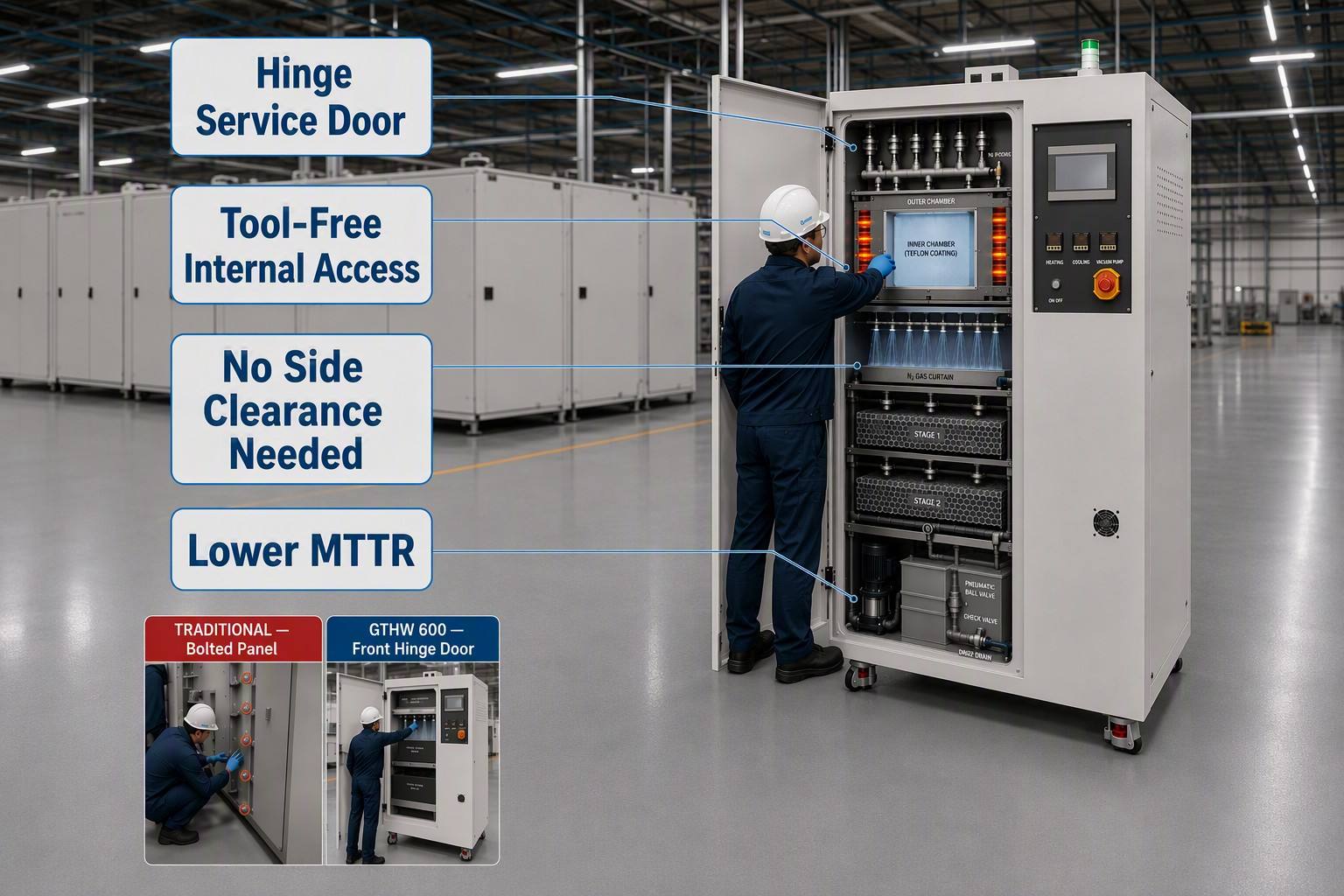
The GTHW 600 hinge door version is designed specifically for this constraint. A front-opening hinge door provides direct access to the reaction chamber, water curtain assembly, and scrubber tower internals without requiring side or rear clearance. A technician can open the door, inspect internal components, and perform routine maintenance — water curtain nozzle cleaning, packing media inspection, sensor verification — without removing the unit from service or clearing adjacent equipment.
This access design directly reduces mean time to repair (MTTR) for the most common maintenance procedures. When preventive maintenance is faster and easier to perform, PM compliance rates increase. When PM compliance increases, unscheduled downtime decreases. The hinge door is not a convenience feature — it is a reliability engineering decision implemented in mechanical design.
Complementing the access design, the PP water tank’s multi-barrier structure and power drain system simplify liquid-side maintenance. The tank can be drained and flushed without disassembly. The pneumatic ball valve and check valve on the drain line prevent backflow during maintenance. The power drain pump’s 16-meter head capability means the drain line can be routed to the fab’s acid waste collection system at elevation, rather than requiring a below-grade gravity drain — another facility integration constraint eliminated.
Part 4: Total Cost of Ownership — Where the GTHW 600 Saves Beyond the Purchase Price
Abatement equipment TCO is dominated by three costs, none of which appear on the purchase order: energy consumption, consumable replacement, and maintenance labor.
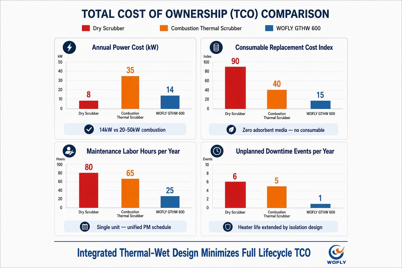
Energy consumption for the GTHW 600 is 14 kW (3-phase, 208V or 380V). For context, a combustion-type thermal abatement system of equivalent capacity typically operates at 20-50 kW to maintain combustion temperature, plus additional energy for pilot flame or sustain ignition. The GTHW 600′s electric heating is applied directly to the reaction chamber — there is no energy lost to heating combustion air, no pilot fuel consumption, and no heat rejected through exhaust gas dilution. Over a 24/7 operating year, the energy savings alone can offset a meaningful fraction of the equipment capital cost compared to combustion alternatives.
Consumable replacement cost — the dominant operating expense for dry scrubbers — is effectively eliminated in the thermal-wet architecture. There is no adsorbent media to purchase, no media changeout labor, and no spent media disposal logistics. The only consumables are municipal water (3-5 LPM, recirculated) and nitrogen (90-150 LPM for purge and gas curtain). For facilities already supplied with bulk N2 and process water, these are existing utility connections, not incremental procurement items.
Heater rod replacement is the principal periodic maintenance expense. The inner/outer chamber isolation design extends heater service life by preventing direct contact between the heating elements and corrosive process gases. While replacement interval depends on operating conditions — temperature setpoint, gas load, and duty cycle — the isolated design consistently achieves longer intervals than direct-contact alternatives. When replacement is required, the hinge door access and front-serviceable chamber design minimize the labor hours per replacement event.
Part 5: Application Coverage Across the Semiconductor Process Chain
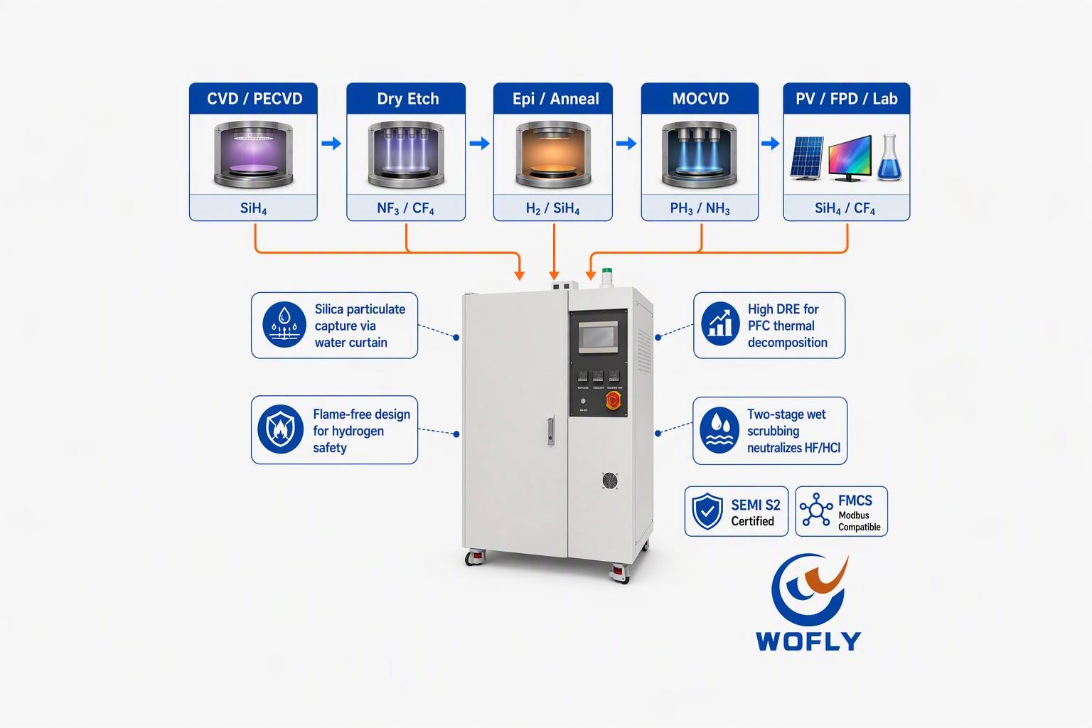
The GTHW 600′s gas compatibility spans the full semiconductor front-end process chain:
CVD and PECVD deposition — silane (SiH4), DCS (dichlorosilane), TEOS (tetraethyl orthosilicate), ammonia (NH3) — used for silicon nitride, silicon oxide, and polysilicon film deposition. The water curtain captures the SiO2 particulate generated from silane oxidation, while the packed tower neutralizes HCl from DCS decomposition and absorbs unreacted ammonia.
Dry etch — NF3, CF4, SF6, CHF3 — used for dielectric and metal etch processes. These gases require high-temperature destruction to break the strong carbon-fluorine and nitrogen-fluorine bonds. The thermal decomposition stage handles this, while the wet scrubbing stage neutralizes the resulting HF and HCl.
Epitaxy and annealing — hydrogen, silane, phosphine (PH3), arsine (AsH3) — used in silicon epitaxial growth and dopant activation. Hydrogen’s flammability and phosphine/arsine’s acute toxicity demand both thermal treatment and alkaline scrubbing. The GTHW 600′s sealed, electrically heated design eliminates the open-flame ignition source that combustion-based abatement introduces into hydrogen service.
Compound semiconductor MOCVD — ammonia, phosphine, arsine, silane — used in LED, laser diode, and HEMT device fabrication. These processes generate large volumes of hydrogen and ammonia that challenge smaller POU units. The 600 LPM capacity accommodates MOCVD exhaust flow rates without requiring multiple parallel scrubbers.
Beyond semiconductor front-end, the GTHW 600 serves photovoltaic PECVD, flat panel display etch, and university research cleanrooms — any facility generating the mixed-gas exhaust that demands integrated thermal-wet treatment.
Media Contact & Company Profile
Shenzhen Wofly Technology Co., Ltd. designs, manufactures, and delivers engineered gas abatement systems including the GTHW 600 Heat-Wet Scrubber and D-200S Dry Scrubber, serving semiconductor fabs, PV manufacturers, compound semiconductor facilities, and research institutions worldwide. All products are supported by factory acceptance testing, on-site commissioning, FMCS integration support, and comprehensive warranty coverage. For gas compatibility evaluations, multi-chamber abatement consolidation studies, or system configuration proposals, contact the WOFLY Abatement Systems Engineering Team at www.szwofly.com.
Post time: Jul-31-2026