1 overview
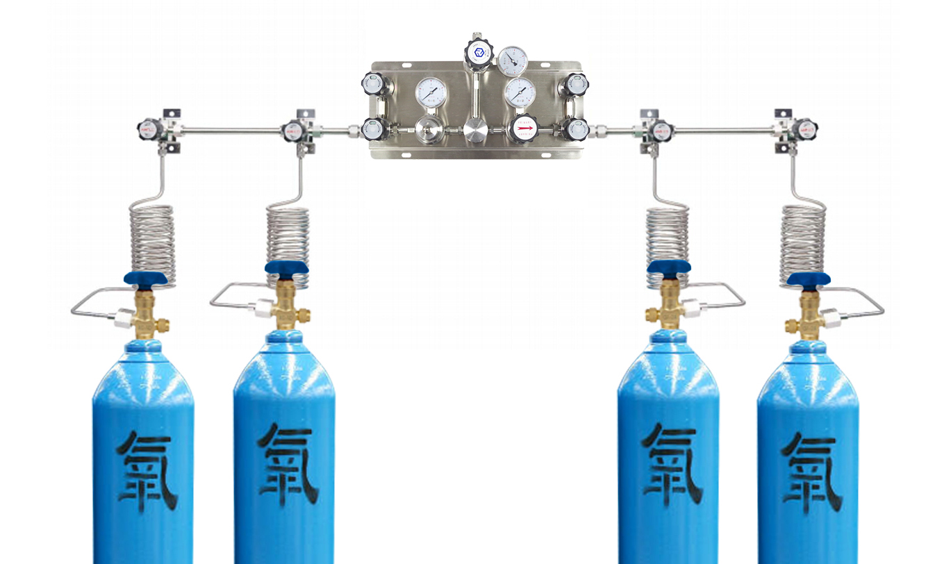
The gas manifold drains the gas from a single cylinder through an associated metal hose/high pressure coil to a common manifold and from there through a single undepressor and at a set pressure to the gas terminal. The dual-side/semi-automatic/automatic/fully automatic switching gas busbar is designed to provide uninterrupted air supply. These forms of bus-bar main air bottle and backup cylinder group adopts double air source structure, main air bottle group when pressure drops to the set pressure, the use of manual or automatic switching mode, will switch to the backup cylinder group, begins with the backup cylinder group, gas to replace main air bottle group, at the same time so as to realize continuous gas supply function. The bus-bar system produced by our company has reasonable structure, simple operation and gas saving, which is an indispensable ideal product for factories and scientific research institutes.
2 warning
The gas manifold system is a high-pressure product. Failure to comply with the following instructions may result in personal injury or property damage. Please read and follow the instructions carefully.
⑴Oil, grease and other flammable materials shall not come into contact with cylinders, bus bars and pipes.Oils and fats react and ignite when they come into contact with certain gases, especially oxygen and laughing gas.
⑵The cylinder valve must be opened slowly as the heat from the gas compression may ignite flammable materials.
⑶Do not twist or bend the flexible pipe with a radius of less than 5 inches. Otherwise, the hose will burst.
⑷Do not heat! Certain materials will react and ignite when they come into contact with certain gases, especially oxygen and laughing gas.
⑸Cylinders should be protected by shelves, chains or ties. An open-ended cylinder, when pushed and pulled hard, will roll over and break the cylinder valve.
⑹Read carefully and install and operate according to the instructions.
⑺The pressure in this manual refers to gauge pressure.
⑻☞ Note: High pressure stop valve handwheel and bottle valve handwheel should avoid direct contact with human body to avoid personal injury.
3 Reference standard
GB 50030 Norm of oxygen plant design
GB 50031 Norm of acetylene plant design
GB 4962 Hydrogen uses safe technology
GB 50316 DesignSpecification for Industrial Metal Piping
GB 50235 Design Specification for construction and acceptance of industrial metal pipeline engineering
UL 407 Manifolds For Compressed Gases
4 System installation and testing
⑴The system should be installed in a ventilated environment, and there should be no fire and no oil signs around it.
⑵First fix the bus-tube bracket to the wall or floor bracket, ensure that the bracket elevation is consistent.
⑶Fix the plastic pipe clamp bottom plate to the bus-pipe bracket, install the bus-pipe, and then fix the pipe clamp cover plate.
⑷Fixed switching system.
⑸For threaded connection system, all valves should be closed during installation. When tightening threads, attention should be paid to not squeeze sealing material into the pipe, so as not to cause system artesiform.For soldered joint systems, all valves shall be open during installation.
⑹After the installation of the system, clean nitrogen should be used for air tightness test, only after passing the air tightness test can be used.
⑺When the installation process is interrupted or the subsequent pipes cannot be connected in time after installation, close the open pipe port in time.
⑻If it is a floor mounting bracket, the mounting bracket can be made as shown in the following figure (bus-pipe mounting bracket).
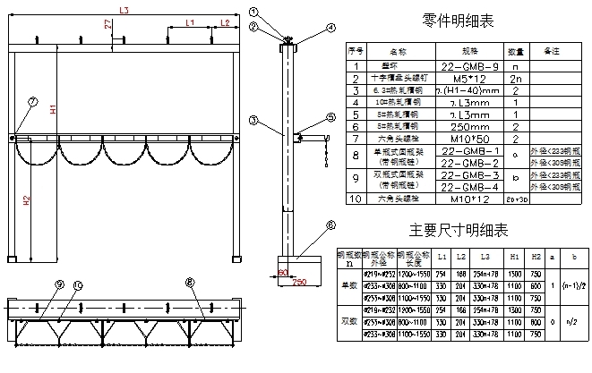
Note: Generally speaking, the user buys the standard model of busbar, its installation method is installed against the wall, its attachment has included installation, fixing bracket, users do not need to make the above bracket. The above image is for those who buy busbars without mounting brackets or non-standard models.
5 System Instructions
5.1 AFK-LOK series automatic switching gas manifold structure diagram
5.2 AFK-LOK series automatic switching gas manifold instruction
5.2.1 According to the system configuration and installation schematic diagram (chart) after good system connection, check carefully whether the threaded connection between the various components and reliable, and confirmed in the system of gas cylinder valve, bus line, bus stop valve, diaphragm valve, valve shut the handwheel clockwise, counterclockwise to open), pressure reducer are closed (unscrew the regulating handle counterclockwise).
5.2.2 Use neutral soapy water to check whether there is air leakage in each component and connection, and then proceed to the next step after confirming that there is no air leakage.
5.2.3 The gas flows from the cylinder through the metal hose/high pressure coil into the bus, and then into the pressure reducing valve, solenoid valve, normally open ball valve, one-way valve in the automatic switch system, and finally into the pipeline system to supply air to the equipment.
5.3 Gas purging and emptying
For large flow of hydrogen, propane, acetylene, carbon monoxide, corrosive gas medium, toxic gas medium, the bus-bar system should be equipped with purge and vent system.For the system with gas purging and venting, please refer to the appendix of this manual for the instructions of the purging and venting system.
5.4 Alarm instructions
Our alarm is divided into AP1 series, AP2 series and APC series, among which AP1 series is switch signal pressure alarm, AP2 series is analog signal pressure alarm and APC series is pressure concentration alarm.The alarm value of common gas pressure alarm is generally set according to the table below.For AP1 series alarms, if you need to change the alarm value setting, please contact our company to reset. For AP2 and APC series alarms, users can follow the attached instrument instruction manual to reset the alarm value.Please follow the instructions on the alarm wiring nameplate to connect the alarm.
|
Gas Type |
The Cylinder Pressure(MPa) |
|
| Standard cylinder O2、N2、Ar、CO2、H2、CO、AIR、He、N2O、CH4 |
15.0 |
1.0 |
| C2H2、C3H8 |
3.0 |
0.3 |
| Dewar O2、N2、Ar |
≤3.5 |
0.8 |
| Others | Please consult our company | |
5.5 Instructions for use of pressure alarm
a.AP1 pressure alarm only has the indicator light to indicate the cylinder gas pressure state in real time, AP2 and APC pressure alarm have the indicator light to indicate the cylinder gas pressure state, but also have the secondary instrument to display the real-time pressure of the left and right cylinders respectively.The following instructions are for pressure alarm only. Please refer to the instructions of gas leak alarm for the concentration alarm of APC series alarm.
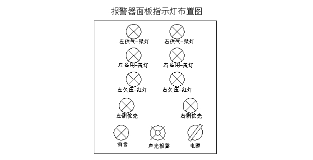
b.AP1, AP2 and APC alarms all use pressure sensors as pressure sensing elements. When the pressure of a side gas cylinder is greater than the alarm value set by the alarm and the gas is supplied preferentially, the corresponding green light will be on.On the contrary, when the pressure of the gas cylinder on the other side is greater than the alarm set alarm value, the yellow light will be on; when the pressure is less than the alarm value, the red light will be on.
c.When the pressure of the side cylinder reaches the alarm value set by the alarm, the green light turns to red and the buzzer starts to sound at the same time.When the yellow light is on the other side, the yellow light turns green and the air is supplied by the lateral system.
d.To avoid noise, press the mute button at this time, the red light continues to light, the buzzer will no longer ring.(For THE CO2 system with travel switch, when the handle contacts the travel switch, make sure that the handle fully contacts the travel switch, and make the travel switch “click” to make the travel switch work, so as to adjust the working state of the two CO2 electric heaters).
e.Replace the empty bottle with the full bottle, the red light on the side turns to yellow, and the instrument alarm indicator is off.
f.Repeat the above steps, the system can achieve continuous air supply requirements.
5.6 Alarm panel indicator function description
5.7 Alarm use warning
Although the signal control part of the alarm system adopts 24VDC safety voltage, there is still 220V AC power supply in the alarm host (relay for heater control and switching power supply), so when opening the cover, be sure that the power switch has been cut off, so as not to cause personal injury.
6 Common faults and maintenance
| Number | Malfunction | Reason | Maintenance and solutions |
| 1 | Inaccurate indication of pressure gauge | Breakdown | Replace |
| 2 | The low pressure side of the pressure reducer rises continuously after the gas is stopped | Seal valve damaged | Replace |
| 3 | The output pressure cannot be adjusted up | Excessive gas consumption/pressure reducer damaged | Reduce gas consumption or increase gas supply capacity |
| 4 | Underventilation | The valve cannot be opened or closed properly | Replace |
7 System maintenance and repair report
The system can be serviced without interrupting air supply (referring to the part that switches from the cylinder to the corresponding valve side). The rest of the system must be serviced after closing all the cylinder valves.
a.When the pressure reducer and high pressure globe valve fail, contact the manufacturer for repair: 0755-27919860
b.Do not damage the sealing surfaces during maintenance.
c.Clean or replace the intake air filter screen and high pressure filter screen of the compressor regularly, so as not to affect the flow of the system.
d.Before cleaning the filter screen of the high pressure filter, the bottle valve must be closed, and the gas in the pipeline part of the system should be emptied.First unscrew the bolt at the bottom of the high pressure filter with a wrench and remove the filter tube for cleaning. Do not clean it with oil or grease. In addition, check whether the sealing gasket is damaged, such as damage, please replace the new gasket (the sealing gasket material is teflon, the user such as homemade, the component machine should be after oiling treatment and dry air or nitrogen dry after use). Finally, install it as is, and tighten the bolts with a wrench.
Post time: Nov-16-2021